Wiring diagram, howtos and diy wiki blog with HD images
Home
› Wiring Diagram Of Turn Signal - turn signal - Jeepster Rescue : If you have the money and the time you can install led turn signals in every turn signal of the car.
Wiring Diagram Of Turn Signal - turn signal - Jeepster Rescue : If you have the money and the time you can install led turn signals in every turn signal of the car.
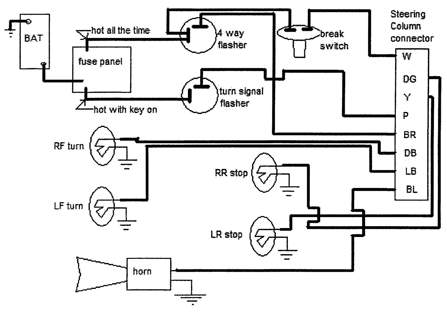
Wiring Diagram Of Turn Signal - turn signal - Jeepster Rescue : If you have the money and the time you can install led turn signals in every turn signal of the car.. To properly read a cabling diagram, one offers to learn how the components within the system operate. Unfortunately i didn't retain the sources. Turn signal wiring diagrams recently i asked on fordbarn if anyone had wiring diagrams for the particular turn signal system (everlasting) that i have mounted on my '29 tudor. The power goes through a fuse panel into the thermal flasher. March 16, 2019 by larry a.
Just remove the blue or orange jumper leads and connect your turn signal adapter leads. Turn signal flasher conversion notes: Diagram buell motorcycle turn signal wiring full version hd quality diagramrt. March 16, 2019 by larry a. Utv turn signal wiring diagram.
Turn Signal Flasher Wiring Diagram — UNTPIKAPPS from www.untpikapps.com Please see the trailer wiring diagram and connector application chart below. I drew it like this, oddly enough, for the sake of clarity, so that one can clearly see what each wire is doing. For example , if a module will be powered up also it sends out a new signal of half. You press and release the momentary switch and then turn the. This version, however, can not support flashing the turn indicator in the tach. It shows the components of the circuit as simplified shapes, and the skill and signal friends between the devices. Though please check with your supplier. Wiring diagram for triumph bonneville rear turn signal from www.triumphrat.net.
To properly read a cabling diagram, one offers to learn how the components within the system operate.
Wiring diagram for triumph bonneville rear turn signal. Otherwise, the arrangement will not function as it should be. Unfortunately i didn't retain the sources. Turn signal flasher relay wiring diagram. Turn signal wiring diagrams recently i asked on fordbarn if anyone had wiring diagrams for the particular turn signal system (everlasting) that i have mounted on my '29 tudor. And now, this is actually the 1st image: To properly read a cabling diagram, one offers to learn how the components within the system operate. Wellborn variety of universal turn signal wiring diagram. Yellow = left turn signal & left brake light 4. It really is intended to help all of the common person in developing a proper program. Led turn signal load resistor wiring diagram (turn signal only) led turn signal load resistor wiring diagram (stop/turn signal) a typical load resistor for a 21 watt turn signal light bulb would have a rating of 50 watts, 6 ohms. Smart turn signal wiring diagram for a honda valkyrie find the wires that control your bikes brake, signal, and tail lights. Please see the trailer wiring diagram and connector application chart below.
From there it goes to the stalk on the steering column. When you employ your finger or even the actual circuit together with your eyes, it may be easy to mistrace the circuit. This version, however, can not support flashing the turn indicator in the tach. Turn signal flasher relay wiring diagram. The following simplified circuit diagram is often used to easily understand how a relay operates:
Technical - how to wire a guide 6002 turn signal switch ... from www.jalopyjournal.com Wires 1 and 8 are both white with a blue stripe. There is actually only one white wire with a blue stripe coming out of the turn signal switch, with the same. The following simplified circuit diagram is often used to easily understand how a relay operates: It shows the parts of the circuit as simplified forms, and also the power and also signal links in between the devices. Just remove the blue or orange jumper leads and connect your turn signal adapter leads. Diagram buell motorcycle turn signal wiring full version hd quality diagramrt. Wiring diagram for triumph bonneville rear turn signal. To fit an extra brake light to my honda cb, there are three wires in the harness on the.
Make your own switch system.
• connect the turn signal adapter yellow wire, directly to the front left amber light lead wire on. The power goes through a fuse panel into the thermal flasher. Turn signal switch is from the streering colum to flasher to tail light, the brake switch. (it's easy!) factory switch most of you will have a hotrod that uses a steering column that has a turn signal switch built in. It includes instructions and diagrams for various kinds of wiring strategies and other things like lights, home windows, and so on. 1967 mustang turn signal switch wiring diagram. Turn signal flasher conversion notes: These guidelines will be easy to comprehend and implement. See * on wiring diagram. Wiring diagram for triumph bonneville rear turn signal. When you employ your finger or even the actual circuit together with your eyes, it may be easy to mistrace the circuit. To properly read a electrical wiring diagram, one offers to find out how typically the components inside the system operate. In the wiring diagram, you will notice what appears to be some extra wires.
To properly read a electrical wiring diagram, one offers to find out how typically the components inside the system operate. Unfortunately i didn't retain the sources. 1967 mustang turn signal switch wiring diagram. See * on wiring diagram. This version, however, can not support flashing the turn indicator in the tach.
Turn Signal Relay Wiring | Wiring Diagram Image from mainetreasurechest.com • connect the turn signal adapter yellow wire, directly to the front left amber light lead wire on. I have included the schematic f. Wiring diagram arrives with numerous easy to stick to wiring diagram instructions. If not, the structure won't work as it ought to be. Unfortunately i didn't retain the sources. See * on wiring diagram. For example , when a module is powered up and it sends out a new signal of 50 percent the voltage and the technician will not know this, he'd think he provides a problem, as this individual would expect a new 12v. The following diagrams show some common relay wiring schemes that use 4 pin iso mini relays.
To properly read a cabling diagram, one offers to learn how the components within the system operate.
For example , if a module will be powered up also it sends out a new signal of half. Model a ford turn signal wiring diagram electrical of f100 65 diagrams 1968 for 66 site signals full switch in 79 1970 mustang dash free 1955 harness 57 truck light 2011 f750 1987 thunderbird 53 help 93 1956 1966 f 250 technical drawings and 1958 ignition 1977 f250 maddening problem ranchero us 1957 chevrolet steering. Wires 1 and 8 are both white with a blue stripe. I drew it like this, oddly enough, for the sake of clarity, so that one can clearly see what each wire is doing. Please see the trailer wiring diagram and connector application chart below. You press and release the momentary switch and then turn the. The following simplified circuit diagram is often used to easily understand how a relay operates: Print the electrical wiring diagram off in addition to use highlighters to be able to trace the circuit. In the wiring diagram, you will notice what appears to be some extra wires. What you need to do is find the wiring diagram for the vehicle the column came from. It includes instructions and diagrams for various kinds of wiring strategies and other things like lights, home windows, and so on. See * on wiring diagram. Diagram dancing led turn signals wiring full version hd quality shipsdiagrams tiburecotrail it.